
- All
- Product Name
- Product Keyword
- Product Model
- Product Summary
- Product Description
- Multi Field Search
English
Views: 0 Author: Site Editor Publish Time: 2026-08-24 Origin: Site


Deep hole drilling relies heavily on precise coolant delivery. Maintaining high pressure, often around 80bar, is vital for flawless chip evacuation and thermal control. However, tool reconditioning involves much more than merely restoring cutting edge geometry. It requires absolute certainty regarding the internal architecture. A microscopic error here can lead to catastrophic tool failure. We must guarantee the regrind process has not compromised, obstructed, or dangerously thinned the walls of the internal coolant channel.
In this guide, we evaluate the technical methods and operational criteria necessary for pristine alignment during tool reconditioning. We will explore how automated verification technologies prevent fluid obstruction and safeguard structural integrity. You will learn how modern metrology techniques vastly differ from traditional manual checks. Ultimately, this article provides the insights needed to protect part quality and optimize your overall regrinding strategy.
Operational Risk: Misaligned grinds around the coolant hole lead to pressure drops, chip packing, tool walk-off, and catastrophic drill failure.
Verification Technologies: Modern verification relies on automated optical profiling and in-process probing rather than manual visual checks.
Equipment Mandates: An advanced CNC Gun Drill Grinding Machine utilizes specialized software to lock the orientation of the teardrop or dual-kidney coolant holes before the grinding wheel engages.
Vendor Evaluation: Selecting a regrinding service or machine requires analyzing their metrology reporting and verifiable runout tolerances, not just cost-per-tool.
Microscopic deviations during the grinding process routinely translate into massive production losses. Operators often view Gun Drill Re-Sharpening as a simple edge-restoration task. This mindset ignores the complex fluid dynamics occurring inside deep holes. When you misalign the primary clearance angle relative to the coolant channel, the drill geometry changes. These slight alterations disrupt high-pressure coolant flow directly at the cutting zone.
Altered hole geometry causes immediate thermal buildup. The restricted coolant flow cannot adequately flush chips up the V-flute. Chips begin packing tightly against the cutting edge. This friction spikes the internal temperature rapidly. Eventually, the carbide tip degrades, or the chips jam completely. A jammed tool snaps inside the workpiece, creating costly downtime and scrapped parts.
Asymmetrical grinding near the coolant channel also triggers severe tool deflection. Uneven cutting forces push the drill off its intended center axis. We call this phenomenon tool walk-off. When the drill wanders, the resulting hole fails straightness and location tolerances. You end up producing out-of-tolerance parts simply because the regrind slightly shifted the tool’s center of pressure.
To avoid these failures, we must define strict success criteria for every reconditioned tool. A successful regrind must achieve the following parameters:
Restore 100% of the original manufacturer's flow dynamics.
Maintain original structural wall thickness around the coolant passages.
Replicate the exact edge profile for balanced cutting forces.
Ensure zero micro-fractures exist along the coolant channel perimeter.
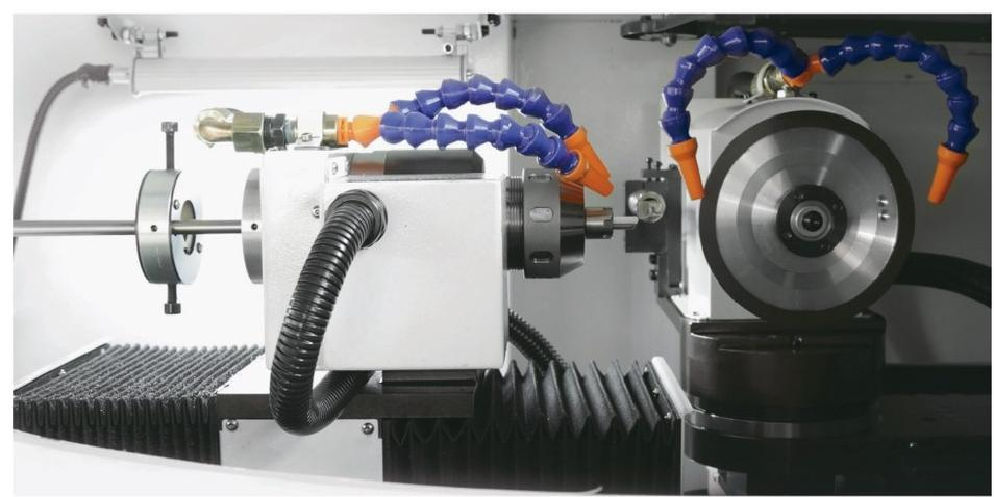
Different tiers of equipment utilize vastly different methods to verify gun drill regrinding alignment. Legacy manual methods rely entirely on operator experience. Modern automated solutions eliminate this human guesswork entirely. They use precise sensors to guarantee perfect orientation before the grinding wheel ever touches the carbide.
Modern CNC systems actively map the drill tip using in-process probing and optical sensors. High-resolution cameras visually locate the exact radial position of the teardrop or dual-kidney holes. Touch probes physically map the flute face. By combining visual data and physical touch points, the machine precisely identifies where the coolant hole sits relative to the cutting edge. This creates a reliable digital baseline for the grinding path.
Once the system maps the tool, automated software compensation takes over. The control system calculates the precise offsets required to grind the primary and secondary clearances. It dynamically adjusts the grinding path to avoid breaching the coolant channel walls. The software locks the orientation. It ensures the grinding wheel removes material only where intended, preserving the critical wall thickness necessary for handling 80bar coolant pressures safely.
Post-grind metrology and flow testing provide the final quality assurance step. Premium facilities utilize digital twin overlay techniques. They scan the reground profile and compare it directly against the original CAD model. Any deviation flags the tool for rejection. Baseline pressure drop bench-testing further validates the tool. Technicians pump fluid through the stationary drill to ensure the spray pattern matches factory specifications.
Verification Method | Technology Used | Accuracy Level | Primary Benefit |
|---|---|---|---|
Manual Visual Check | Magnifying loop, operator sight | Low / Inconsistent | Low initial setup cost |
In-Process Touch Probing | Physical CNC probes | High | Maps flute geometry physically |
Optical Profiling | Sub-micron cameras | Very High | Locates internal hole orientation radially |
Digital Twin Overlay | 3D scanning software | Ultimate Precision | Validates final grind against CAD specs |
You must rigorously evaluate your chosen equipment or external service partner. Assessing their capability to verify alignment requires looking past simple cost-per-tool metrics. You need absolute transparency regarding their metrology capabilities and clamping systems.
First, demand superior sensor resolution and metrology capabilities. The inspection systems must possess sub-micron optical resolution. They need the ability to detect microscopic wall thinning near the coolant outlet. Furthermore, the equipment must generate verifiable geometric inspection reports. If a vendor cannot hand you a digital profile report of your reground tip, they likely rely on outdated manual checks.
Fixture repeatability dictates the overall success of the operation. You must assess the clamping systems used during the grinding cycle. Pneumatic or hydraulic chucks provide rigid, repeatable clamping. Standard V-blocks often allow micro-rotation of the drill body. Even a one-degree rotation shifts the hole orientation out of tolerance. Precision chucks prevent this shifting, locking the tool firmly along its axis.
Finally, insist on compliance and operational transparency. Demand documented standard operating procedures (SOPs). These documents must clearly define how technicians verify wall thickness limits post-grind. High-pressure coolant applications require rigid adherence to safety margins. If a reground tool bursts during a high-pressure cycle, it ruins the workpiece. SOPs ensure technicians never approve a drill featuring dangerously thin walls.
Request digital overlay reports showing the CAD model versus the reground tip.
Audit the clamping mechanisms to ensure hydraulic or precision pneumatic systems are standard.
Ask vendors for their documented wall thickness minimums regarding 80bar coolant applications.
Verify they perform post-grind flow or pressure testing before shipping tools back.
Ignoring technical realities during tool reconditioning leads directly to compromised tools. Several common mistakes plague the industry, mostly stemming from human error or inadequate machinery. Understanding these pitfalls helps you safeguard your machining processes.
Over-grinding and wall breakthrough represent the most dangerous risks. Operators sometimes miscalculate the indexing angle. The grinding wheel cuts too deeply into the primary clearance. It slices entirely into the coolant channel. Even if it does not break through completely, it leaves a foil-thin wall. Once the spindle fires high-pressure coolant through the tool, this weakened wall blows out instantly.
Another major mistake involves ignoring flute taper and helix variations. Custom step gun drills often feature changing geometries. The coolant hole position shifts radially along the tool length as it tapers. Operators cannot assume a static orientation for these complex tools. If they lock the drill assuming a standard straight-flute geometry, the wheel will inevitably misalign the clearance angles near the step transitions.
Legacy manual grinding limitations continue to haunt manufacturing floors. Relying on an operator's "rule of thumb" introduces unacceptable variance. Human eyes cannot accurately judge micron-level orientations. This manual approach creates a high scrap risk. Digital verification remains the only reliable method for preventing asymmetrical cuts and ensuring perfect fluid dynamics.
Deciding how to manage tool re-sharpening requires a structured framework. You must weigh the benefits of purchasing dedicated machinery against the convenience of outsourcing to a specialized vendor.
When tool volume reaches a critical mass, upgrading to an in-house CNC Gun Drill Grinding Machine becomes highly logical. Conduct a break-even analysis based strictly on tool life extension and scrap reduction. Dedicated machines featuring built-in optical alignment verification eliminate human error. They restore tools faster and more accurately. Over time, reducing the frequency of scrapped parts justifies the initial capital expenditure.
If you choose to outsource, you must thoroughly vet external partners. Ask them specific technical questions. Ask, "What optical inspection systems do you use to verify coolant hole clearance?" Request sample digital profile reports from previous jobs. Evaluate their facility readiness. A reliable vendor operates like an extension of your own quality control department.
We recommend a phased rollout approach. Never commit your entire tooling inventory to a new vendor or new process immediately. Conduct a pilot test first. Submit a small batch of end-of-life tools. Have the vendor recondition them. Once returned, evaluate their alignment precision. Test their flow performance under actual cutting conditions. Monitor the spindle load and chip evacuation rates. Only scale up the relationship once the pilot batch proves flawless.
Strategy | Ideal Scenario | Primary Advantage | Key Requirement |
|---|---|---|---|
In-House CNC Upgrade | High daily volume of worn tools | Total control over alignment specs | Capital budget for optical machinery |
Outsourcing | Low/variable tool usage | No internal machinery maintenance | Rigorous vendor vetting & auditing |
Phased Pilot Test | Transitioning to a new vendor | Minimizes risk of total batch failure | Bench-testing capabilities in-house |
Gun drill regrinding alignment acts as a critical variable in deep hole drilling success. It is never an optional quality check. Proper alignment ensures coolant flows efficiently, chips evacuate cleanly, and cutting forces remain perfectly balanced. A tiny misstep during the grinding phase destroys tool integrity and ruins expensive parts.
Transitioning to verifiable, CNC-controlled alignment protects your part quality continuously. Automated probing and optical profiling remove human guesswork. They lock the tool orientation securely, preventing accidental wall breakthroughs. This precision ultimately maximizes your tool return on investment by extending the usable life of every single drill in your inventory.
Take action immediately to secure your machining processes. Audit your current regrinding tolerances today. Request detailed metrology data from your current external vendors. If you handle re-sharpening internally, evaluate your facility readiness for automated grinding equipment. Prioritizing digital verification today prevents catastrophic tool failures tomorrow.
A: Safe wall-thickness minimums depend heavily on your specific coolant pressure requirements. High-pressure systems running at 80bar demand thicker structural boundaries to prevent blowout. Generally, technicians maintain at least a 0.2mm to 0.3mm wall margin, though OEM specifications for specific carbide grades ultimately dictate the absolute minimum safe distance.
A: Yes, advanced optical recognition software can map the hole profile and flag major irregularities. However, the software has limits. If the hole deformation indicates severe structural fatigue or internal micro-fracturing, the system will pause the cycle. Operators must then scrap the tool, as regrinding cannot fix internal material failure.
A: The fastest method involves spindle-through coolant pressure bench-testing. Before cutting any metal, mount the tool and activate the high-pressure coolant pump. Visually verify the spray pattern and check the machine gauge for abnormal pressure drops. An irregular spray or pressure spike indicates internal obstruction or hole misalignment.
A: Asymmetrical grinding relative to the coolant hole shifts the tool's center of pressure. Even if the cutting edges feel razor-sharp, unequal clearance angles create unbalanced radial forces during rotation. This imbalance pushes the drill off its axis, causing deflection and walk-off regardless of the actual edge sharpness.


