
- All
- Product Name
- Product Keyword
- Product Model
- Product Summary
- Product Description
- Multi Field Search
English
Views: 0 Author: Site Editor Publish Time: 2026-08-03 Origin: Site


The physical arrangement of abrasive wheels determines your operational ceiling. In modern tool manufacturing, this setup acts as either your primary bottleneck or your greatest enabler. Improper configurations frequently lead to excessive mechanical tool changes. They increase collision risks and severely compromise spindle stability. These errors directly impact your cycle times. They also elevate your cost-per-part metrics unnecessarily. You need a highly systematic approach to maximize your machine output.
This article provides a rigorous technical evaluation framework. We assess physical pack setups to help you achieve operational excellence. You will learn how to optimize software-to-hardware kinematics effectively. We also explore actionable steps to reduce setup-induced errors on your shop floor. Mastering these strategic elements allows you to transform your grinding process. You can turn unpredictable setups into a highly profitable, scalable operation.
Strategic grinding wheel pack configuration minimizes non-productive tool change times and maximizes continuous machining cycles.
Proper sequencing and spacing within the pack are critical for enabling advanced tool axis control and avoiding software-predicted collisions.
Off-machine presetting and rigorous calibration are mandatory for scaling 5-axis grinding operations without sacrificing tolerance accuracy.
Balancing aggressive material removal (fluting) with finishing operations (gashing/relief) on a single spindle requires strict attention to load distribution and wheel wear rates.
We must shift our focus away from individual wheel performance. You need to prioritize total pack efficiency instead. A properly engineered grinding wheel pack configuration directly extends autonomous runtimes. It reduces complex setup transitions and maximizes overall machine utilization. Operators often chase minor gains in individual grit performance. They ignore the massive time lost during mechanical spindle swaps. Your success metric should measure the volume of finished tools produced per continuous cycle.
Consolidating your fluting, gashing, and relief wheels changes everything. You place them into a single optimized assembly. This strategy drastically reduces mechanical tool changeovers. Every mechanical swap stops production and introduces positioning variables. A unified assembly allows your machine axes to transition seamlessly between roughing and finishing. You keep the spindle engaged with the workpiece longer. This continuous engagement slashes your cycle time across high-volume batches.
Poor setups carry heavy hidden costs. Accelerated wheel wear remains a primary issue. Incorrect configurations often block high-pressure coolant from reaching the grinding zone. Starved grinding zones cause thermal damage and rapid grit degradation. You also face increased machine downtime for mid-cycle dressing. Operators must constantly stop production to correct form errors. These interruptions destroy your profit margins. You must engineer your packs to support fluid delivery and consistent wear rates.
You must evaluate your placement logic carefully. Always place the heaviest fluting wheels closest to the spindle bearing. This specific placement minimizes arbor deflection under heavy grinding loads. Deflection ruins tight aerospace tolerances instantly. You must also assess clearance requirements for complex geometries. End mills, step drills, and profile tools demand distinct approach angles. You need adequate spacer width between wheels to prevent physical hub interference. Failure to calculate this clearance guarantees fixture collisions.
Mixing different abrasive types requires strict attention. Diamond and CBN wheels exhibit different mass densities. Mounting varying diameters on a single arbor affects your kinetic balance profoundly. Poor balance induces harmonic vibration across your machine chassis. This vibration destroys surface finish quality and wears spindle bearings prematurely. You must manage motor torque effectively. Place aggressive material removal wheels where they leverage maximum spindle rigidity. Keep smaller finishing wheels positioned further outward.
Pack density dictates your fluid dynamics completely. Tight wheel spacing alters the trajectory of high-pressure coolant. A dense assembly often creates an air barrier. This barrier deflects coolant away from the critical cut zone. You require adjustable manifold configurations to penetrate these dense setups. Correct nozzle targeting prevents severe thermal damage to the workpiece. Precision coolant delivery also flushes swarf effectively. Proper flushing prevents wheel loading during deep fluting passes.
The chart below outlines baseline recommendations for balancing abrasives and coolant flows based on typical wheel positions.
Operation Type | Arbor Position | Abrasive Match | Coolant Pressure Requirement |
|---|---|---|---|
Deep Fluting | Closest to Bearing | Diamond / CBN (Coarse) | High (70+ Bar) |
Gashing | Middle | Diamond / CBN (Medium) | Moderate to High |
OD Relief | Outermost | Diamond / CBN (Fine) | Moderate (Precision Targeted) |
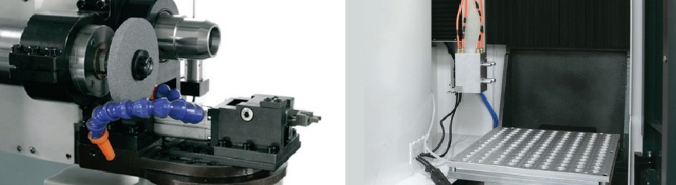
Your CAM software interprets the physical hardware arrangement constantly. It uses this data to calculate safe approach vectors. It also determines complex retract paths during multi-axis interpolation. The digital twin must exactly match your real-world setup. If your digital wheel thickness varies by just a fraction, the simulation fails. Operators rely on software to push feed rates safely. Validating your kinematic models ensures the machine executes code exactly as intended.
Software simulation has distinct limitations. Physical pack spacing often deviates from digital assumptions due to spacer compression. You cannot rely purely on virtual collision avoidance. Operating a 5-Axis CNC Tool Grinding Machine demands absolute dimensional accuracy. You must use accurate 3D wheel modeling to prevent spindle-to-fixture crashes. This modeling must include wheel hubs, intermediate spacers, and clamping flanges. Missing any of these components in your software library guarantees a physical collision.
Multi-wheel setups restrict specific tilt and pivot angles. A long arbor limits how far your A and C axes can rotate safely. Large diameter fluting wheels often block the approach path for smaller gashing wheels. You must plan these restrictions during the initial programming phase. These physical limits dictate which tool geometries you can manufacture in a single clamping. You must sequence your paths to avoid interference between the inactive wheels and the machine collet.
Off-machine presetting is absolutely necessary for modern production. You should evaluate the implementation of optical presetters immediately. These devices measure exact wheel profiles and core radii. They also verify total pack lengths before installation onto the machine. Using an optical presetter eliminates on-machine probe time entirely. You regain valuable spindle hours previously lost to manual touch-offs. A pre-qualified assembly drops into the machine ready for immediate production cycles.
You must establish strict baselines for radial and axial runout. Even minimal runout destroys edge geometry on high-performance end mills. We recommend maintaining radial runout below 0.002mm across a multi-wheel setup. Follow these critical steps during calibration:
Clean the arbor shaft and wheel bores meticulously.
Mount the heaviest fluting wheel closest to the base.
Measure and insert precision-ground spacers.
Torque the clamping flange to the manufacturer's exact specification.
Verify final radial and axial runout on an optical presetter.
Assess your truing strategies based on production volume. Continuous on-machine dressing keeps wheels sharp during aggressive fluting. However, it consumes cycle time rapidly. Periodic off-machine truing offers an alternative for complex geometries. You true the entire assembly on a dedicated machine offline. This trade-off preserves your primary machine's uptime. Choosing the right strategy depends on your grit types and wheel bond hardness.
The following table illustrates the typical tolerances you must achieve during off-machine presetting.
Measurement Metric | Acceptable Tolerance | Primary Impact on Production |
|---|---|---|
Radial Runout | < 0.002 mm | Prevents chatter marks and uneven wheel wear. |
Axial Runout | < 0.005 mm | Ensures precise step lengths and accurate corner radii. |
Pack Length Stack-up | < 0.010 mm | Maintains software collision models and Z-axis offsets. |
You face strict physical and spatial limits when adding wheels. Overloading the arbor creates dangerous cantilever effects. A heavy, extended Grinding Wheel Pack generates severe harmonic vibration. This vibration translates directly into poor surface finishes on the tool flutes. You also stress the spindle bearings beyond their design limits. You must balance the desire for fewer tool changes against the reality of mechanical rigidity. Never exceed the spindle manufacturer's maximum weight rating.
You must address stack-up tolerances honestly. Spacers deform under high clamping torque. They also expand during intense operating temperatures. Aluminum spacers expand faster than steel arbors. This thermal expansion shifts your wheel positions mid-cycle. Your software assumes the wheels remain static. Thermal drift causes your grinding paths to wander, ruining tight tolerances. Always use premium hardened spacers. You must torque your flanges consistently using a calibrated wrench to prevent erratic compression.
You need a framework for evaluating your current tooling strategy. Standardize your assemblies to eliminate guesswork.
Audit your crash logs: Identify if specific extended setups cause recurrent collisions.
Measure true cycle times: Compare your actual run times against CAM simulated times.
Standardize tool families: Build dedicated setups for specific tool classes like aerospace routers or medical bone drills.
Inspect spacers regularly: Discard any spacers showing signs of galling or irregular compression.
Wheel pack configuration is not just a routine setup task. It operates as a core production strategy. The physical layout dictates the absolute limits of your 5-axis machining capabilities. A poorly designed assembly restricts your spindle movement. It increases your cycle times and drives up scrap rates. Conversely, a highly optimized arrangement unlocks continuous, autonomous production. It allows your software and hardware to work in perfect synchronization.
We strongly recommend standardizing your configurations based on tool families. Stop custom-building packs for every unique job order. Dedicated, pre-qualified setups ensure predictable scalability. This standardized approach guarantees compliance with tight aerospace and medical manufacturing tolerances. You protect your machine investments. You also empower your operators to focus on process improvement rather than constant setup troubleshooting. Take control of your grinding kinematics today.
A: You can typically mount three to five wheels effectively. This maximum depends strictly on spindle length limits and weight restrictions. Adding more wheels pushes you past the point of diminishing returns. Excessive weight induces harmonic vibration and ruins surface finish quality. Always consult your specific machine load charts before expanding an assembly.
A: A longer arbor dramatically expands your physical collision zone. It strictly limits your A and C axis rotation capabilities. Extended setups often hit workholding fixtures or tailstocks during deep pivot movements. You must physically verify these limits against your CAM software digital twin to prevent severe machine crashes.
A: Yes, combining them reduces cycle times significantly. However, you must carefully evaluate grit contamination and coolant pressure. Aggressive fluting demands high-pressure coolant, which can deflect off large roughing wheels and starve smaller finishing wheels. You must sequence them properly and use adjustable coolant manifolds to ensure success.


