
- All
- Product Name
- Product Keyword
- Product Model
- Product Summary
- Product Description
- Multi Field Search
English
Views: 0 Author: Site Editor Publish Time: 2026-08-31 Origin: Site


Inconsistent manual drill resharpening causes numerous production bottlenecks on the modern shop floor. It routinely leads to increased spindle load, poor hole tolerance, and premature tool failure. Machinists often underestimate the exact precision required to restore a drill to its original factory condition.
Point angle and chisel edge geometry ultimately dictate thrust force and heat dissipation during any cutting operation. When operators sharpen cutting tools by hand, they rarely replicate these critical micro-geometries accurately. The resulting mismatch creates massive friction. This friction destroys tool life and immediately stalls cycle times.
Precision tool maintenance demands much more than simply restoring a sharp edge. It requires the right mechanical process and dedicated equipment to match original OEM specifications consistently. Achieving this consistency ensures long-term production scalability. In this guide, we will explore exactly how drill geometry affects machining dynamics. You will learn to optimize specific point angles, manage chisel edges, and standardize your entire resharpening workflow.
Geometry dictates performance: Altering the point angle during resharpening directly impacts cutting lip engagement and material compatibility (e.g., 118° vs. 135°).
Chisel edges create bottlenecks: An unoptimized chisel edge contributes up to 60% of total thrust force; proper web thinning or split-point grinding drastically reduces this friction.
Repeatability requires equipment: Relying on free-hand grinding introduces micro-asymmetries. Utilizing a dedicated drill re-sharpening machine ensures exact facet replication and verifiable ROI through extended tool life.
The point angle determines the actual thickness and width of the chip produced during drilling. As the drill advances into the workpiece, the point angle dictates how the cutting lips engage the material. A steeper angle creates a shorter cutting lip. A flatter angle creates a longer cutting lip. This difference changes the distribution of the cutting force.
When you spread the cutting load over a longer lip, the resulting chip becomes thinner. Thinner chips dissipate heat much faster. This heat transfer protects the tool margin and prevents the cutting edge from breaking down. Understanding this physical relationship forms the foundation of proper drill point angle resharpening.
Manufacturers typically supply drills with either a 118-degree or a 135-degree point angle. Choosing the correct angle for your specific material is crucial.
118° Angle: This angle works perfectly for softer materials like aluminum, mild steel, and plastics. It provides a more aggressive cutting lip. The aggressive tip easily penetrates soft alloys. However, it remains highly prone to "walking" across the workpiece if the chisel edge is too wide. You must monitor the center web carefully.
135° Angle (Flatter profile): You need this angle for harder alloys, stainless steel, and titanium. The flatter profile engages the material much faster. It reduces chip thickness and actively spreads the cutting load across a wider area. This distribution minimizes localized heat buildup.
Shops sometimes attempt to reprofile a 118-degree drill into a 135-degree drill. You must assess the risks of changing OEM angles before doing this. Arbitrary angle adjustments carry severe consequences. You cannot simply flatten the point angle without also altering feed rates.
If you flatten the angle but maintain the same aggressive feed rate, you will overstress the cutting lips. This results in rapid cutting edge degradation. Reprofiling also requires corresponding adjustments to the lip relief angle. A flatter point angle usually demands a slightly different clearance angle to prevent the heel of the drill from rubbing against the workpiece.
Failing to thin the web after changing a 118-degree drill to 135 degrees.
Ignoring the spindle speed requirements for the newly flattened angle.
Leaving the lip relief angle unaltered, causing immediate friction and tool failure.
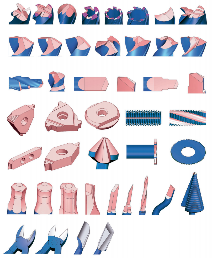
The standard chisel edge sits at the very center of the drill bit. Surprisingly, it does not actually "cut" material. Instead, it extrudes material. Because the cutting speed at the dead center is zero, the chisel edge merely pushes and smears the metal outward until the primary lips can shear it away.
This extrusion process causes incredibly high localized heat. It requires massive spindle thrust to push the non-cutting center through the metal. In fact, an unoptimized chisel edge generates up to 60% of the total thrust force required for the entire drilling operation. This excess thrust accelerates machine wear and limits your maximum feed rates.
To overcome this thrust bottleneck, modern machining relies on split points and aggressive web thinning.
Grinding a split point fundamentally changes the tool geometry. It converts the dead center into active cutting edges. By notching the center web, you create a positive rake angle right at the chisel edge. The tool now cuts from the very center outward.
We correlate chisel edge thinning directly to a reduction in drill walking. A thinned web allows the drill to bite into the material instantly upon contact. This instant engagement eliminates the need for center-punching or running separate pilot holes. You streamline your operations and eliminate entire steps from your machining process.
Optimized chisel edges deliver immediate, measurable improvements in automated CNC environments. You can track these improvements across several key performance indicators:
Tighter Hole Tolerances: A split point keeps the drill perfectly centered. It prevents bell-mouthing and ensures the hole remains true to size from top to bottom.
Reduced Cycle Times: Lower thrust force allows you to program much more aggressive feed rates. You can drill faster without overloading the machine spindle.
Lower Scrap Rates: Eliminating drill wander prevents out-of-tolerance holes. You ruin fewer parts and waste less expensive material.
Extended Spindle Life: Reducing the downward pressure on your CNC spindle saves the internal bearings from premature wear.
Conical grinding represents the traditional method for sharpening standard twist drills. The mechanism creates a smooth, continuous clearance curve behind the cutting edge. As you look at the flank of the drill, it resembles a section of a cone.
This use case proves sufficient for general-purpose drilling. It works well for manual drill presses and basic maintenance tasks. However, conical grinding inherently results in a wider chisel edge. Because it only utilizes a single sweeping curve, it does not provide the specialized clearance needed for high-speed CNC applications.
Multi-facet grinding takes tool performance to a much higher level. The mechanism uses distinct primary and secondary clearance planes rather than a continuous curve. A 4-facet drill features two primary cutting planes and two secondary clearance planes. A 6-facet drill adds two more planes specifically for the split point.
This use case remains essential for high-performance drilling. The primary facet provides superior edge strength right behind the cutting lip. The secondary facet drops away sharply to provide maximum clearance for chip evacuation. This complex geometry delivers precise centering and handles extreme cutting speeds effortlessly.
Multi-facet geometries are nearly impossible to achieve manually. You cannot hold a drill against a bench grinder and precisely create four distinct, perfectly symmetrical planes. These advanced profiles require highly calibrated grinding setups and dedicated fixtures.
Comparison of Resharpening Approaches
Feature | Conical Grinding | Multi-Facet Grinding |
|---|---|---|
Clearance Geometry | Continuous curved sweep | Distinct flat planes |
Chisel Edge Width | Generally wider, requires separate thinning | Narrow, highly optimized for centering |
Edge Strength | Moderate | Superior (Primary facet supports the lip) |
Application | General shop use, manual drilling | High-speed CNC, hard alloys, aerospace |
Sharpening Method | Can be done manually or via machine | Strictly requires dedicated machinery |
When an operator sharpens a tool by hand, minute errors occur. A 1-degree difference between the two cutting lips might look perfectly fine to the naked eye. However, the mechanical reality is disastrous.
If one lip sits 1 degree higher or longer than the other, that single lip engages the material first. It is forced to do 100% of the work. The drill point shifts off the central axis of rotation. The single working lip cuts an oversized hole while experiencing double the thermal load. This micro-asymmetry easily halves tool life and causes catastrophic edge chipping.
Relying on tribal knowledge for tool maintenance poses a severe operational risk. If only one senior machinist knows how to grind a specific drill correctly, your production halts when they are absent.
Evaluating this risk reveals the stark contrast between manual methods and standardized operations. Process-driven operations do not rely on "feel" or steady hands. They rely on mechanical fixtures and fixed cams. By moving away from operator dependency, you guarantee that an apprentice can sharpen a tool just as accurately as a master machinist.
In highly regulated industries like aerospace or medical machining, part consistency is non-negotiable. Verifiable tool geometry acts as a critical compliance metric.
You cannot use hand-ground tools when cutting aerospace-grade titanium components. The risk of work-hardening the material due to a rubbing, asymmetrical drill is too high. Quality Assurance (QA) protocols demand that every tool entering the CNC carousel meets exact, documented specifications. Standardized resharpening guarantees this compliance.
Establish strict discard criteria for drills that have been shortened beyond 30% of their flute length.
Implement a tagging system to track how many times a specific drill has been resharpened.
Audit hand-ground drills under an optical comparator to demonstrate asymmetry to shop personnel.
We must compare the standard deviation of off-hand grinding to the precision of a purpose-built system. Hand grinding produces a massive standard deviation in point angles, lip heights, and clearance angles. You might get lucky once, but you cannot repeat it consistently.
A high-quality Drill Re-Sharpening Machine removes the human wrist from the equation entirely. It locks the tool into a rigid fixture. It guides the tool against the grinding wheel at exact, mathematically perfect angles. The precision becomes absolute.
When selecting a machine, you must evaluate three critical dimensions to ensure it meets your production needs.
The collet system is the heart of the grinder. Ensure the machine chucks on the drill margins accurately. If the collet grips the flutes unevenly, the tool will spin out of concentricity. A precision collet maintains perfect concentricity, guaranteeing the chisel edge remains dead center during grinding.
Evaluate how the machine dictates the point angle and lip relief automatically. Premium grinders use internal cam mechanisms. As you rotate the chuck, the cam dictates exactly how much material the wheel removes. This mechanical guidance creates the perfect clearance angle without any guesswork.
You cannot machine modern materials efficiently without split points. Therefore, split-point functionality represents a must-have feature for any modern high-speed steel (HSS) and solid carbide drills. A dedicated Drill Bit Grinder will have a specific port or alignment slot designed purely for thinning the web and creating a perfect split point in seconds.
Guide your procurement team to calculate the exact return on investment. Do not base the decision solely on the initial capital expenditure. Instead, calculate your current tool replacement costs over a six-month period. Factor in the hourly cost of machine downtime when an operator stops a CNC cycle to replace a prematurely failed drill.
When you add up the costs of scrapped parts, wasted materials, and new tool procurement, the math speaks for itself. Justifying the capital expenditure for a dedicated grinder becomes incredibly easy. The equipment often pays for itself rapidly through preserved tool life and uninterrupted machining cycles.
Extending tool life is ultimately a strict mathematical equation. It relies heavily on exact point angles, symmetrical cutting lips, and optimized chisel edges. When you deviate from OEM geometries, you instantly increase thrust forces, generate excess heat, and destroy your cutting tools.
Moving away from manual sharpening is the single most effective way to eliminate these variables. We strongly prompt you to audit your current scrap rates and analyze your monthly tool replacement expenditures. Consider transitioning to a standardized, machine-driven resharpening process. By utilizing precision equipment, you will lock in tighter tolerances, lower your cycle times, and maximize the operational efficiency of your entire machine shop.
A: Yes, but doing so typically requires a capable drill re-sharpening machine to correctly re-establish the lip relief and thin the web to accommodate the flatter angle. You must also adjust your CNC feed rates, as the new 135-degree angle changes the chip load and cutting dynamics entirely.
A: Drill walking is almost always caused by uneven cutting lip lengths or a chisel edge that is too wide and not properly split. If one lip is longer than the other, it hits the metal first, instantly pushing the drill point off its true center axis.
A: The web gets thicker as the drill is ground further down the flute. Web thinning should occur during every resharpening cycle once the drill has been shortened past its initial 10-15% of flute length. Skipping this step drastically increases thrust force.
A: Yes, if the shop runs strict tolerances or machines hard alloys. The reduction in scrapped parts and new tool procurement often offsets the machine cost within months. It also eliminates dependency on single operators, ensuring anyone can perfectly restore a tool's geometry.


